
Cisco Packet Tracer
What you will need
Section titled “What you will need”In order to follow this lab, you will need your own personal device and to download Cisco Packet Tracer. The current latest version for Packet Tracer is 9.0.1.
Important Concepts
Section titled “Important Concepts”The OSI Model
Section titled “The OSI Model”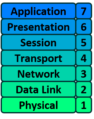
OSI Layers
Section titled “OSI Layers”-
Physical
Section titled “Physical”The Physical layer is the literal wires and the electricity that flows through them in a network.
The only components that operated on this layer are, as mentioned previously, wires.
There are no protocols running on this layer, this is the initial data that is 1’s and 0’s (bits).
If all you ever needed to do was send data between two computers, this is the only layer you’d need. You just hook up a cable and call it a day.
-
Data Link
Section titled “Data Link”The Data Link layer is where networking stuff actually starts occuring. Here, bunches of bits get combined into one frame and metadata is appended to this frame with information about its source and destination.
On the Data Link layer, hosts are described by their MAC address. This is a set of 12 hexadecimal characters given to the device by the manufacturer.
In order to route traffic on this layer (by MAC address), we use a switch. It keeps a table of MAC Addresses, called a CAM table, and uses that to figure out where to send the frames to.
-
Network
Section titled “Network”At a certain point, networks get too large for us to just use switches with really long lists of meaningless device ID’s. This is where the Network layer comes in.
At the Network layer, hosts are described by their IP address. This is a set of 4 bytes assigned to the device by a server or manually configured by a person. These addresses can be assigned, changed, and taken away at will.
Just like the Data Link Layer, in order for data to be interpreted, a bunch of frames are gathered up into one packet and metadata about the source and destination IP is appended.
Many switches these days are able to operate on the Network layer nowadays, but the quintessential router of Network layer traffic is called, well, a router.
-
Transport
Section titled “Transport”Finally, the last layer we are going to talk about is the Transport layer, the layer responsible for transporting data between networks.
The Transport layer follows suit with the others and combines a bunch of packets into one segment/datagram.
The metadata applied here is the source and destination port, which is a number from 0-65535 which accompanies the IP address. We will talk more about ports later.
Protocols
Section titled “Protocols”A protocol is just a documented way of doing something, and it means the same thing when it comes to networking. It is just a commonly used method for communicating information, and, depending on the information you’re sending, you need to use a different protocol.
ARP stands for address Resolution Protocol, and is the protocol for obtaining the IP address for a device from its MAC address and vice versa.
The device making an ARP request just sends out a message to every other device asking “Who has this IP?” and hopes that it gets a responsible
ICMP is the Internet Control Message Protocol, a protocol used for the ping command.
It operates on layer 3, sending out a small packet to a specific IP that just asks for a response
TCP is the Transmission Control Protocol, one of two protocols that operate on the Transport layer.
TCP is a protocol that attempts to maximize reliability. It starts with what is called a three-way handshake to ensure that the source can contact the destination, and then sends over numbered segments and makes sure the receiver says that they received each packet.
This is the protocol used for websites, email, or file transfers.
UDP is the User Datagram Protocol, and is basically TCP’s exuberant twin.
UDP wants to maximize speed, so it just shoots off packets and doesn’t bother to check whether the receiver received any of them.
This is the protocol used for streaming video and other protocols trying to maximize speed, like DNS and NTP.
Internet Protocol Details
Section titled “Internet Protocol Details”IP Space
Section titled “IP Space”The complete range of IPv4 addresses is from 0.0.0.0 to 255.255.255.255, which allows for 4 BILLION unique IPs. That’s a whole lot of IPs, but we also have a whole lot of things that need IPs.
BUT THERE IS A SOLUTION, (and its not IPv6 yet, because nobody wants to adopt it)
The current solution is very simple: Private and Public IP addresses
Public IPs
Section titled “Public IPs”Whenever devices from two different networks communicate with each other, they will always go through the networks’ routers before making it to their destination. So really, if we’re trying to minimize IPs, all we have to do is give them the IP of the other devices router and let the router figure out where to go from there. The IPs that the routers are assigned are called Public IPs.
Private IPs
Section titled “Private IPs”But how does the router know how to route between devices on it’s network now that they don’t have an IP address? Well, through a new IP address of course! This IP address only has to be unique WITHIN the network, so it is called an Private IP. Devices on two different networks can have the exact same Private IPs, but Public IP’s are all unique.
Now we’ve forced the routers to handle the tricky job of translating between public and private IP addresses (just so we’re clear, routers now have both a public and private IP, each on a different connection).
The fix for this is something I’ve mentioned before: Ports! (I’m so great at forshadowing)
The router utilizes port numbers to decide which host in their private network to relay information to.
Example
Section titled “Example”That was a lot of yap, so lets give an example so you can get even more yap.
Imagine you’re on your laptop visiting Google (a real fantasy world, am I right?). Your device has some private IP address such as 192.168.1.101, and your router has the private IP address 192.168.1.1. You know that Google’s IP is 8.8.8.8, so you make a request from that IP. Inevitably your packet makes its way to the router, because no one in your private network has that IP. Your router converts your packet into a segment, deciding that you will be using Port 54321 for this Google visit. It sends that info to Google, along with its Public IP (we’ll go with 128.123.123.123). Now when Google sends info back to 128.123.123.123, it will give the destination port of 54321, and the router will know that this data is for your laptop at 192.168.1.101!
Private IP Ranges
Section titled “Private IP Ranges”There are 3 ranges of IPs that are reserved to be used only for private IP’s, for the sake of not confusing the poor routers. They are:
- 192.168.0.0 - 192.168.255.255
- 172.16.0.0 - 172.31.255.255
- 10.0.0.0 - 10.255.255.255
- Bonus: 127.0.0.0 - 127.255.255.255 reserved for localhost
That is why you see these IP addresses SUPER often whenever you’re doing stuff on an internal network (which is most of the time). The first value in this range is called the Network Address and the last value is the Broadcast Address. Both are reserved, meaning you can not/should not set a device to one of those IPs.
The Whole Story
Section titled “The Whole Story”After seeing those ranges, you may be thinking (or you may not, who am I to assume) that there are some patterns in each of those IP ranges.
That is because of the secret underlying structure of IPs that I’ve been keeping from you this whole time..
The Whole Story (cont.)
Section titled “The Whole Story (cont.)”Because IP addresses are just sets of 4 bytes, we can rewrite any IP address in base 2 and get some nice properties. For example, the private IP ranges can be rewritten as:
- 11000000.10101000.00000000.00000000 - 11000000.10101000.11111111.11111111
- 10101100.00010000.00000000.00000000 - 10101100.00011111.11111111.11111111
- 00001010.00000000.00000000.00000000 - 00001010.11111111.11111111.11111111
Notice how the first 16, 12, and 8 bits for each of these ranges stays the same? Hmm if only there was a way to use this to create a shorthand for writing IP address ranges..
Subnet Mask and CIDR
Section titled “Subnet Mask and CIDR”I have INCREDIBLE news, there IS a way to use this to create a shorthand! Two shorthands actually.
The first is the subnet mask, a set of 4 bytes that shows the range of IPs that a device in a network can take on. The subnet mask has 1’s in the places where the bits for the IP are “locked” (all IPs on the network share the exact same value for that particular bit), and 0’s in the places where a device can choose either a 0 or a 1 for that bit. The 1’s on the subnet mask are called the network bits because they define the network, and the 0’s are the host bits because they define the host on the network.
The second is CIDR notation, which can be used when the subnet mask is a series of 1’s followed by series of 0’s. For instance, the CIDR notation for the private IP ranges are 192.168.0.0/16, 172.16.0.0/12, and 10.0.0.0/8.
Subnetting
Section titled “Subnetting”Now that we know how to describe IP ranges, we can divide our network up into sub-networks, subnets!
For example if you have a network with the IP range 192.168.0.0/24, and want to break it up into 2 (maybe it’s your house and you want a guest and a family subnet), you can cut the range in half.
These two ranges (192.168.0.0 - 192.168.127.255 and 192.168.128.0 - 192.168.255.255) can be represented simply as 192.168.0.0/25 and 192.168.128.0/25.
Network Configuration
Section titled “Network Configuration”Now let’s learn some actually useful information!
Static IP Config
Section titled “Static IP Config”In order for your device to function well, you need to set up configure these things:
- IP Address: Your private IP
- Subnet Mask: The address range for your internal network
- Default Gateway: The private IP for your router
- DNS Server: The IP for your DNS server (could be either private or public)
But luckily, in the real world you don’t even need to do that!
DHCP is the Dynamic Host Configuration Protocol, which automatically configures new devices that connect to a network.
DHCP is the reason you can just put in the WiFi password when your at someone’s house, rather than do research on the structure of their internal network.
Finally, the Lab!
Section titled “Finally, the Lab!”Components
Section titled “Components”When you open up Packet Tracer, you should see a blank canvas, this is where we will be plaing in our networking components.
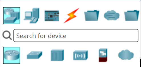
Lets start with a host! At the bottom left corner of your screen, you should see two rows of objects separated by a search bar. We’ll call this the Device Types Toolbar.
Components (cont.)
Section titled “Components (cont.)”The top row lets you select a specific genre of devices (network devices, end devices, etc.)
The bottom row lets you select the type of device within a given genre (network devices => routers, etc.). Based on what you select in the top and bottom rows, a new set of devices will appear in the toolbar to the right of the Device Types Toolbar, which we’ll call the Devices Toolbar.
Click on the second icon in the top row of the Device Types Toolbar, and then find the PC icon in the Devices Toolbar, and drag two PC’s onto the Main Canvas in the center of your screen.
Connecting Devices
Section titled “Connecting Devices”Next, lets place a switch in to let these two lonely fellas talk to each other. I’ll let you figure out how to place in a 2960 Switch (Hint: it uses similar steps to how we placed in the PC’s)
Now we can connect things up! Select the Connections icon in the Device Types Toolbar to reveal the different cables we can use. The Flash symbol in the Devices Toolbar can be used to automatically connect two devices, but we don’t have that in the real world so we’re gonna click on copper straight-through, a cable we DO have in the real world.
Connecting Devices (cont.)
Section titled “Connecting Devices (cont.)”After clicking on the Copper Straight-Through icon, we can click on PC0 and select FastEthernet0, which is the ethernet port on this PC. We can connect this up to the switch by clicking on it and selecting any of it’s ports; I’ll select FastEthernet0/1.
After a moment, there should be two green triangles at either end of your cable. But we don’t need to wait for those to appear, we can go ahead and do the same thing with PC1, connecting it up to FastEthernet0/2 on the switch.
IP Configuration
Section titled “IP Configuration”Now TECHNICALLY our devices our connected, but in order to do anything useful, they need to be able to communicate on the Network Layer, which means they need IPs. We’ll use the private IP range 192.168.0.0/24 for our network.
To do this, you can click on PC0, go to the “Desktop” tab, and click on the “IP Configuration” app. From there, make sure your IP is set to “Static” and input the IPv4 address 192.168.0.2 (we’re saving .1 for later). You’ll notice that the subnet mask is automatically filled in.
Do the same for PC1, but give it the address 192.168.0.3.
Testing
Section titled “Testing”Lets see if all that work actually amounted to anything by sending an ICMP ping from one computer to another.
Stay on PC1 and X out of the “IP Configuration” App. Now click on the “Command Prompt” app. From there, type in:
ping 192.168.0.2If everything is configured correctly, you should get replies from the IP you pinged.
Adding a Router
Section titled “Adding a Router”Goodie goodie, we can send packets within our network, but I still can’t access Google and watch silly dog videos, so what’s the point?
Sadly, I’m not going to be able to do that with Packet Tracer, but we can still make our network able to contact other networks. All we need is a router!
Grab the 4331 Router from the Devices Toolbar and place it in the canvas. Then connect the GigabitEthernet0/0/1 interface on the router to the FastEthernet0/3 interface on the switch with a Copper Straight-Through Wire.
Configuring the Router
Section titled “Configuring the Router”In order to configure the router, click on it and open up the “Config” tab. Then, click on the interface we hooked up to the switch (GigabitEthernet0/0/1), and type in an IP address.
It is common convention that the gateway router’s IP is the lowest address in the range (besides the network address), so we’ll give it the IP 192.168.0.1 (thats why we saved this IP).
Then, set the port status to “On”. From here, we can also set the default gateways for our PCs by going to the “IP Configuration” app and setting the Default Gateway to the router’s IP.
Two is Better than one
Section titled “Two is Better than one”We have a router, but a router isn’t good for anything if it can’t, well, route. So let’s create a new network for us to route to.
The address range for this network will be 172.16.1.0/24. Try to use this notation to identify the subnet mask and the IP of our default gateway!
We’ll start just as we did before by plopping in a new 2960 Switch. Then we’ll bring in a 4331 router and give it the default gateway IP and the subnet mask you totally figured out based on our CIDR notation IP range.
DHCP Server
Section titled “DHCP Server”Since we’ve now configured a grand total of three devices, we can consider ourselves seasoned network administrators and delegate some work to others. In the case of our new network, we’ll be delegating work to a machine.
Grab a Server from the Devices Toolbar and place it on the canvas. Connect it up as per usual to our switch. We can give it the IP of 172.16.1.100 with a subnet mask of 255.255.255.0 and a default gateway of 172.16.1.1 the same way we assigned IPs to the PCs.
(Note: Go back and change your router config if you didn’t get this default gateway and subnet mask!)
Configuring DHCP
Section titled “Configuring DHCP”Now it’s time to configure! Click on your server and go to the “Services” tab. From here, we will change the default gateway (172.16.1.1). We have not configured a DNS server, so no need to worry about that.
For the Start IP Address and Subnet Mask, put in our network address and subnet mask (hint: it should already be autofilled!)
Now, all we have to do is click save and set the service to “On”. Now we should hopefully get assigned an IP address automatically, meaning we’re free from the drudgery of static IPs.
Testing
Section titled “Testing”In order to test that everything is working we’ll place a PC into our network. This time, instead of configuring a static IP in the “IP Configuration” app, we’ll just turn on DHCP with the toggle at the top of the app.
If everything is configured correctly, your PC should receive an IP address!
Make sure that the IP, subnet mask, and default gateway make sense (e.g. 172.16.1.2, 255.255.255.0, and 172.16.1.1)
Wireless Fireless
Section titled “Wireless Fireless”Now that we don’t have to manually configure every end device on our network, we can go absolutely nuts with what we put on it. In the case of this lab, we’ll be adding some wireless devices.
Find the AP-PT (Access Point), which is under Network Devices => Wireless Devices. Connect Port 0 of the access point up to a port on the switch.
WiFi Configuration
Section titled “WiFi Configuration”To configure the access point, click on it and go to the “Config” tab. Click on “Port 1”
Set the:
- SSID: Homelab
- Authentication: WPA2-PSK
- PSK Passphrase: insecure_pass
- Encryption Type: Keep it as AES
Make sure the Port is “On” in the top right corner and then you’re good to exit out.
Adding a Wireless Device
Section titled “Adding a Wireless Device”Lets set up a wireless device to connect to this Access Point. To do this, we can find the Laptop component and place it in.
For some reason, our laptop doesn’t have WiFi card yet, so lets add that by clicking on it and going to the “Physical” tab. Before we swap elements of the laptop, we need to turn it of by clicking the circular power button on the left of the laptop with a light below it.
Now that the laptop is off, we can remove the ethernet port by dragging it off the laptop. We can then drag a “WPC300N” into the slot we just freed up. Then turn the laptop back on.
Configuring the Device
Section titled “Configuring the Device”In order to connect to the WiFi, we can go to the “Desktop” tab on the laptop and go to the “PC Wireless” app. From here, click on connect.
After waiting a moment, our Homelab network should come up. We can click the “Connect” button next to “Refresh” and type in our preshared key (insecure_pass)
Now you can exit out and change your IP config to DHCP in the “IP Configuration” app. To test your connection, you can try to ping the other computer on your network.
Bridging the Gap
Section titled “Bridging the Gap”Finally, lets connect our two networks. We can do this through, you guessed it, Copper Straight-Through Cable! Connect the cable to both of the routers’ GigabitEthernet0/0/0 interfaces.
Now we need to give them their external IPs. First we’ve got to decide what our external network will be. I’ll say that our external network is 128.0.0.0/8. Now all we have to do is give our routers IPs that are within this MASSIVE range.
To do this we can click on each router, go to the “Config” tab, and input their IP address and subnet mask (I’m going to force you to figure out the subnet mask for yourself). I’ll give the router for the 192.168.0.0/24 network the IP 10.0.0.1 and the router for the 172.16.1.0/24 network the IP 10.0.0.2.
Testing
Section titled “Testing”Now lets see if we can ping one of the PCs on the 192 network from a host on our 172 network.
Try to send a ping to 192.168.0.2 (Our first PC) from the PC on the 172 network.
ping 192.168.0.2Does it work?
The reason we can’t reach our other network is because we haven’t taught out routers how to route. There are many different protocols for this, but the one we’ll be using today is by far the simplest to set up (for small networks).
It’s called RIP, which stands for Routing Information Protocol, or Resting in Peace, which is what your network will be doing if you tried to use this in a large enterprise network, because it scales TERRIBLY
The way RIP works is that, every 30 seconds, every router broadcasts their routing table and tells the world which networks they can route to. When sending packets, routers use this info to find the path to the destination that requires the fewest “hops”
Setting up RIP
Section titled “Setting up RIP”In order to set up RIP, we need to tell the routers which networks they are directly next to. We can do this by clicking on each router, going to the “Config” tab, and clicking on “RIP”
Next we need to type in the networks that each router is directly next to (the networks they have interfaces on). For our first router, we can type in 10.0.0.0 and click “Add”, and then do the same for 192.168.0.0. For router 2, we add 10.0.0.0 and 172.16.1.0
Testing Better
Section titled “Testing Better”Now go back to your PC or laptop on 172.16.1.0/24 and try and contact 192.168.0.2. If everything is configured right, you should get a response!
Note: The first packet or two might get dropped, but that’s just the network figuring out where stuff is, and happens in real life to!